Languor: Boolean Logic
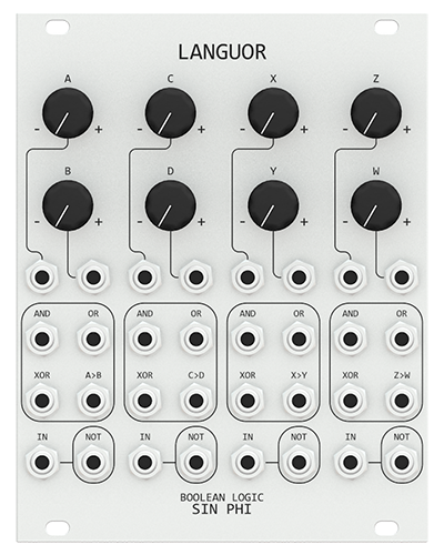 The Langour is a boolean logic engine that can perform and, nand, or, nor, xor, xnor, not, comparator and any combination of those functions. Each of the four logic cells has two attenuverting inputs with and, or, xor, comparator and not boolean functions. The inverse logic functions can be obtained by feeding the output into the not gate. For the comparator, as an example, the A>B function through the not gate gives B>A as output. The Langour is a powerful tool to create gates that can be used to program sequencers, switches, envelopes and other modules.
Many of the inputs in the Langour module are normaled to each other or reference voltages. This enables rapid programing with minimal patching. The first input of each cell (A, C, X, Z) is normaled to the input of the not gate. The A input is normaled to +10V, the C input is normaled to A, the X input is normaled to C, and the Z input is normaled to C. The second input of each cell (B, D, Y, W) is normaled to +10V; this allows the attenuverter to create a DC voltage to compare to.
CC BY-NC-SA 4.0
Schematic
PCB Layout
 |
 |
Panel Design
Bill of Materials
Tuning and Calibration
Connect the OUT output to an oscilloscope. Use the mid setting of the RANGE switch. Set to cycle on the CYCLE switch and use the manual trigger TRIG switch. Set rise and fall to minimum. Turn the SHAPE potentiometer fully clockwise. Rise and fall times should be equal. If they are not adjust the symmetry trimmer. Repeat for the other side.
Patch Programming
NAND
Put the output of the AND gate into the NOT gate. To get the NAND output, take the output of the NOT gate.
NOR
Put the output of the OR gate into the NOT gate. To get the NOR output, take the output of the NOT gate.
NXOR
Put the output of the XOR gate into the NOT gate. To get the NXOR output, take the output of the NOT gate.
B>A
Put the output of the A>B gate into the NOT gate. To get the B>A output, take the output of the NOT gate.